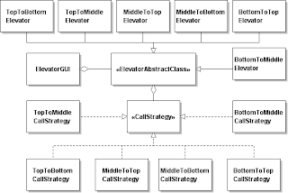
The first line of thinking about this problem was similar to that of the stopwatch. The elevator can be in one of three states: top, middle, or bottom corresponding to the third floor, second floor and first floor respectively. But our state diagram takes on extra states due to more than one behavior possible for a particular state. For example, the elevator in the top state can go either to the middle state (second floor) or to the bottom state (first floor). Thus, just like the stopwatch, we model the states of the elevator depending on what the user does.
The second degree of freedom in this application is the behavior of a "called" elevator (the user pushes the ""CALL" button) verses the behavior of the elevator when the user "takes" the elevator (uses one of the "GO" buttons). When a user "takes" the elevator to a floor, the textfield announcement is that the elevator arrives, the door opens and the user exits. When a user "calls" the elevator (uses one of the "CALL" buttons), the textfield announcement is that the elevator arrives and the door opens. Thus, a response to a "CALL" button cannot be implemented as though it were a response to a "GO" button. Another part of the problem is that there are two "GO" buttons on each floor. This makes it relatively easy to assign to a listener what state should handle a click on a "GO" button.

This UML class diagram does not show the classes involved in the GUI aspects of the application. This UML class diagram shows the classes involved in the behavior of the elevator - specifically how it handles a user "taking" the elevator to another floor and how a user "calls" the elevator from a floor different from the floor the elevator currently resides. The solution shown is available here.

No comments:
Post a Comment