Showing posts with label State Design Pattern. Show all posts

Tuesday, March 10, 2009

Challenge Four: Answer - Bridge Design Pattern

Challenge Four

The first line of thinking about this problem was similar to that of the stopwatch. The elevator can be in one of three states: top, middle, or bottom corresponding to the third floor, second floor and first floor respectively. But our state diagram takes on extra states due to more than one behavior possible for a particular state. For example, the elevator in the top state can go either to the middle state (second floor) or to the bottom state (first floor). Thus, just like the stopwatch, we model the states of the elevator depending on what the user does.
The second degree of freedom in this application is the behavior of a "called" elevator (the user pushes the ""CALL" button) verses the behavior of the elevator when the user "takes" the elevator (uses one of the "GO" buttons). When a user "takes" the elevator to a floor, the textfield announcement is that the elevator arrives, the door opens and the user exits. When a user "calls" the elevator (uses one of the "CALL" buttons), the textfield announcement is that the elevator arrives and the door opens. Thus, a response to a "CALL" button cannot be implemented as though it were a response to a "GO" button. Another part of the problem is that there are two "GO" buttons on each floor. This makes it relatively easy to assign to a listener what state should handle a click on a "GO" button.
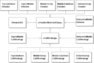


This UML class diagram does not show the classes involved in the GUI aspects of the application. This UML class diagram shows the classes involved in the behavior of the elevator - specifically how it handles a user "taking" the elevator to another floor and how a user "calls" the elevator from a floor different from the floor the elevator currently resides. The solution shown is available here.
Sunday, March 8, 2009

Challenge Four: Doktat's Elevator

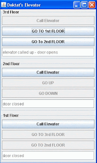
Challenge Four involves an application that crudely simulates a three-floor elevator as shown in the schematic below. The code for the ElevatorGUIshell can be downloaded here. The challenge is to program this application without the use of any conditional logic.

The application starts with the elevator at the first floor with 'GO' buttons enabled and 'CALL' buttons on floors two and three also enabled. At this point the elevator can go to the second or third floor in response to either the 'GO' buttons on the first floor or the 'CALL' buttons on either the second or third floors.

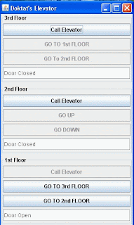
Assume the user has clicked on the 'GO TO 2nd FLOOR' button. The configuration of the elevator application should appear as shown in the figure below.


Having gone to the second floor, the 'GO' buttons on the second floor are now enabled and the 'CALL' button for the second floor disabled. The 'GO' buttons on the first floor are now disabled but the 'CALL' button for the first floor is now enabled. The configuration of the third floor remains unchanged. The textfield for the first floor indicates the door has now closed and the textfield for the second floor indicates the elevator has arrived, the door has opened and the user has exited.

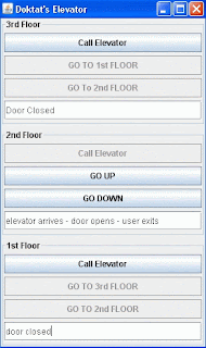
Assume now that a user has clicked on the 'CALL' button on the third floor. The configuration of the elevator should appear as shown in the schematic below.

Having arrived at the third floor the textfield indicates the elevator has arrived and the door has opened. Note that this message is different from the message shown when the elevator arrived at the second floor as the result of the user using the 'GO' button. Thus, the message shown is different in the textfield of the respective floor depending on whether the elevator was called to that floor or a user took the elevator to that floor. Again, the 'GO' buttons are now activated for the third floor but the 'CALL' button on the third floor is disabled. The textfield on the second floor indicates the door has closed and the 'CALL' buttons for both the second and first floors are enabled.

A solution employing no conditional logic will be available here.

Saturday, February 28, 2009

Challenge Two - State Design Pattern

In Programming Without Ifs Challenge One we identified the varying behavior which depended on the state of the calculator, and abstracted it with the introduction of a Strategy Design Pattern. Then when the calculator switched from the pre-operator mode to the post-operator mode, the calculator model also switched to the appropriate strategy. Thus, the calculator model was not kept in a state of ignorance. It didn't need to employ conditional logic to ask itself what state it was in to decide what to do - it already knew. The logic for switching between the strategies, ie., knowing when a change of state occurred and what to do about it, stayed on the calculator model. Our refactoring just implemented it in a different way. In Programming Without Ifs Challenge Two, we use the State Design Pattern, which moves the knowledge for what to do to the classes that characterize the state machine. Challenge Two involves programming a stopwatch.

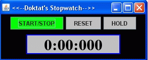
Consider the scheme of the stopwatch interface shown below.


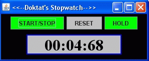
The stopwatch is started by clicking on the Start/Stop button. The watch is started as evidenced by the time label and the 'HOLD' button is activated. The watch can now be stopped or suspended as shown in the figure below.


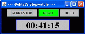
The suspended mode is for timing splits. By clicking on the 'HOLD' button again, the watch will catch up to it's original timing and subsequent suspensions can again occur indefinitely. The watch can be stopped by clicking on 'START/STOP' from either the suspended mode or the running mode. After stopping the watch, the 'RESET' button will be activated as shown below.


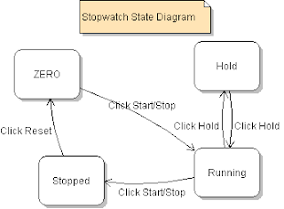
After clicking on 'RESET' the watch will return to its starting mode as shown in the first schematic. A state diagram for the stopwatch is shown below.


Download for the code for the stopwatch with conditional logic and refactor such that no conditional logic is used to manage the state dependencies of the application. It may be necessary to create more states than shown in the state diagram above.