From my studies of graduate students in the Masters of Software Engineering program at Carroll University, I think that most object-oriented programmers are procedural programmers using an object-oriented language. A more detailed discussion of this is found here. Are you one of these programmers? The following five exercises can be solved without using any conditional logic. If you can't solve these problems, study them to expand your scope and add some tools to your toolbox. Each problem has working code for an unsolved example (uses conditional logic) and a solved example (no conditional logic). Study these examples to expand your capabilities. Then, you will have more than a hammer in your toolbox and not every problem will appear as a nail. Having these tools will help you build more complex "Enterprise" systems without creating BBOM's (Big Balls of Mud). As always, stick to the adage, "PROGRAM TO THE INTERFACE AND NOT TO THE IMPLEMENTATION."
Exercise I: Bergin Swing Calculator (Solution: Strategy Design Pattern)
Exercise II: Doktat's Stopwatch (Solution: State Design Pattern)
Exercise III: Dependency Inversion Principle
Exercise IV: Doktat's Elevator (Solution: Bridge Design Pattern)
Exercise V: Doktat's Pizza Place (Solution: Decorator Design Pattern & Reflection)
Monday, July 13, 2009
Saturday, March 21, 2009
Challenge Five Answer: Decorator Design Pattern and Reflection
One approach to this problem is to have a class representing each of the possible pizza types and extra toppings. For example, one class might be ThinCrustOnionPepperoni whereas another might be ChicagoStyleAnchovy. Thus, if the user selects the Thin Crust radio button and Onion check box, an instance of ThinCrustOnion would be instantiated and used for the source of data needed to display the description and the cost. This is a brittle solution because it is very difficult to add and subtract components from the menu. New classes with all the various combinations of components must be pre-constructed and this type of class definition isn't necessary when we can build the class dynamically. The Decorator Design Pattern is ideally suited for this kind of situation because it permits us to add responsibilities to our constructed object dynamically. The code discussed in the following can be downloaded here.
The GOF text speaks of the Decorator Design Pattern as a "degenerate composite with only one component." Java programmers encounter this design pattern when they begin using classes in the java.io package in a manner similar to this:
DataInputStream dis = new DataInputStream(new FileInputStream(new File("name")));.
All of the classes referenced in the preceding statement are subclasses of java.io.InputStream and each one has a constructor that takes an InputStream argument. How can this practice of dynamically building responsibilities into the desired class be employed in our pizza place?
Consider the following statement as an alternative to our previous solution where pre-constructed classes represented the range of pizza types and toppings.
PizzaComponent pizza = new Onion(new Pepperoni(new ThinCrust()));
An application employing this type of solution to our problem is easier to change. All that is required is to add or omit the relevant component and change the GUI. An application using this approach is available here.
However, since this discussion appears in the context of programming without if's, we still have more progress to make. Our application is still using conditional logic to determine which combination of radio button and check boxes was selected and then subsequently builds the desired pizza. Wouldn't it be nice to have a way to build a list of the desired components and then when the user proceeds to the checkout, the list of components is used to dynamically build our pizza object? Then it wouldn't be necessary to use any conditional logic to determine which components were to be included as decorators on our pizza. We can't build a list of object instances because the components are built from instances of each other. Can our list be composed of the class names? Yes - and we can use reflection combined with the Decorator to build our pizza without the use of conditional logic.
The following discussion introduces us to another GOF design pattern, the Builder Design Pattern, but we will save the discussion of Builder for another time. In the application available here a few new features have been introduced to obviate the need for conditional logic. Subclasses of JRadioButton and JCheckBox, SelfListeningJRadioButton and SelfListeningJCheckBox, respectively, were created to relieve the GUI from having to determine (with conditional logic) which button or box was selected. In other words we are now giving each button or checkbox the responsibility of listening to itself and also knowing what to do when it is selected. Subclasses of these self-listening components, such as OnionCheckBox are instantiated and passed a reference to an instance of PizzaComponentBuilder which is used to store the list of class names of the components selected by the user. In other words, each time a user selects a radio button or a checkbox the class name of that pizza component is added to a List on the builder object.
There are more features included in this application that need to be discussed. To deal with users changing their minds while selecting components, the capability to unselect a checkbox was included. Since selecting a checkbox results in adding the class name to the list in the builder, de-selecting a checkbox must remove the class name from the list. This capability was added with the use of the Strategy Design Pattern (discussed already in Challenge One: The Bergin Calculator application) and accounts for the 'on' and 'off' strategies associated with each of the components. With the use of these strategies the checkbox components do not need to ask themselves what state they are in to perform their responsibilities.
Because the method we are using in this application is much easier to implement, we have included the capability to select one of the other pizza types, ie., Chicago Style, Pan or M'Waukee Style. Again, the Strategy Design Pattern was used to obviate the need to use conditional logic to determine which of the pizza types was to serve as the base component in the construction of the pizza.
Now we consider the way the PizzaComponentBuilder constructs the pizza object from the List containing the class names of the components. As mentioned above we combine the use of reflection with the Decorator Design Pattern to build our pizza object. Consider the method shown below which contains all that is needed. The strComponents object is a List which contains the class names of the components as Strings.
public PizzaComponent buildComponentUsingReflection()
{
newComponent = currentStrategy.getBaseComponent();
Object[] arg = { newComponent };
iterator = strComponents.iterator();
while (iterator.hasNext())
{
try
{
someClass = Class.forName((String) iterator.next());
constructors = someClass.getConstructors();
newComponent = (PizzaComponent) constructors[0].newInstance(arg);
}
catch (Exception ex3)
{
System.out.println("something wrong in PizzaComponentBuilder 3 " + ex3);
}
arg[0] = newComponent;
}
strComponents.clear();
return newComponent;
}
The first statement from the method above determines which pizza type was selected, ie., Thin Crust, Pan, etc., and the second step assigns to the object array the inner most (nucleus) component of our pizza object. The iteration is started that goes through the list of class names that will be the components used to build the pizza object. The first statement in the try-catch block creates an instance of Class that represents the class identified by the class name (String) in the array. The first time through the iteration finds this class to be one of the pizza types which was placed in the array in the above-described steps. The next step obtains the array of Constructors (Constructors[])which was defined with class scope and not shown in the method (see code package). The next step containing the invocation of contructors[0].newInstance(PizzaComponent) is not immediately obvious. This is the step that instantiates the class represented in the first step, which will be the pizza type the user selected. For purposes of discussion, assume the type is Thin Crust and therefore the object will be an instance of ThinCrust class. The signature of Contructor.newInstance requires the arguments to the constructor to be passed as an array containing the argument objects. In our case the array argument, 'arg' contains only one component, the instance of ThinCrust set in the second statement of the method. Then, once the new PizzaComponent is instantiated and we leave the try-catch block, we assign to the 'arg' array the object that was just instantiated. On the subsequent iteration, this is the argument used in the constructor for the next level of our decorated pizza object.

The GOF text speaks of the Decorator Design Pattern as a "degenerate composite with only one component." Java programmers encounter this design pattern when they begin using classes in the java.io package in a manner similar to this:
DataInputStream dis = new DataInputStream(new FileInputStream(new File("name")));.
All of the classes referenced in the preceding statement are subclasses of java.io.InputStream and each one has a constructor that takes an InputStream argument. How can this practice of dynamically building responsibilities into the desired class be employed in our pizza place?
Consider the following statement as an alternative to our previous solution where pre-constructed classes represented the range of pizza types and toppings.
PizzaComponent pizza = new Onion(new Pepperoni(new ThinCrust()));
An application employing this type of solution to our problem is easier to change. All that is required is to add or omit the relevant component and change the GUI. An application using this approach is available here.
However, since this discussion appears in the context of programming without if's, we still have more progress to make. Our application is still using conditional logic to determine which combination of radio button and check boxes was selected and then subsequently builds the desired pizza. Wouldn't it be nice to have a way to build a list of the desired components and then when the user proceeds to the checkout, the list of components is used to dynamically build our pizza object? Then it wouldn't be necessary to use any conditional logic to determine which components were to be included as decorators on our pizza. We can't build a list of object instances because the components are built from instances of each other. Can our list be composed of the class names? Yes - and we can use reflection combined with the Decorator to build our pizza without the use of conditional logic.
The following discussion introduces us to another GOF design pattern, the Builder Design Pattern, but we will save the discussion of Builder for another time. In the application available here a few new features have been introduced to obviate the need for conditional logic. Subclasses of JRadioButton and JCheckBox, SelfListeningJRadioButton and SelfListeningJCheckBox, respectively, were created to relieve the GUI from having to determine (with conditional logic) which button or box was selected. In other words we are now giving each button or checkbox the responsibility of listening to itself and also knowing what to do when it is selected. Subclasses of these self-listening components, such as OnionCheckBox are instantiated and passed a reference to an instance of PizzaComponentBuilder which is used to store the list of class names of the components selected by the user. In other words, each time a user selects a radio button or a checkbox the class name of that pizza component is added to a List
There are more features included in this application that need to be discussed. To deal with users changing their minds while selecting components, the capability to unselect a checkbox was included. Since selecting a checkbox results in adding the class name to the list in the builder, de-selecting a checkbox must remove the class name from the list. This capability was added with the use of the Strategy Design Pattern (discussed already in Challenge One: The Bergin Calculator application) and accounts for the 'on' and 'off' strategies associated with each of the components. With the use of these strategies the checkbox components do not need to ask themselves what state they are in to perform their responsibilities.
Because the method we are using in this application is much easier to implement, we have included the capability to select one of the other pizza types, ie., Chicago Style, Pan or M'Waukee Style. Again, the Strategy Design Pattern was used to obviate the need to use conditional logic to determine which of the pizza types was to serve as the base component in the construction of the pizza.
Now we consider the way the PizzaComponentBuilder constructs the pizza object from the List
public PizzaComponent buildComponentUsingReflection()
{
newComponent = currentStrategy.getBaseComponent();
Object[] arg = { newComponent };
iterator = strComponents.iterator();
while (iterator.hasNext())
{
try
{
someClass = Class.forName((String) iterator.next());
constructors = someClass.getConstructors();
newComponent = (PizzaComponent) constructors[0].newInstance(arg);
}
catch (Exception ex3)
{
System.out.println("something wrong in PizzaComponentBuilder 3 " + ex3);
}
arg[0] = newComponent;
}
strComponents.clear();
return newComponent;
}
The first statement from the method above determines which pizza type was selected, ie., Thin Crust, Pan, etc., and the second step assigns to the object array the inner most (nucleus) component of our pizza object. The iteration is started that goes through the list of class names that will be the components used to build the pizza object. The first statement in the try-catch block creates an instance of Class that represents the class identified by the class name (String) in the array. The first time through the iteration finds this class to be one of the pizza types which was placed in the array in the above-described steps. The next step obtains the array of Constructors (Constructors[])which was defined with class scope and not shown in the method (see code package). The next step containing the invocation of contructors[0].newInstance(PizzaComponent) is not immediately obvious. This is the step that instantiates the class represented in the first step, which will be the pizza type the user selected. For purposes of discussion, assume the type is Thin Crust and therefore the object will be an instance of ThinCrust class. The signature of Contructor.newInstance requires the arguments to the constructor to be passed as an array containing the argument objects. In our case the array argument, 'arg' contains only one component, the instance of ThinCrust set in the second statement of the method. Then, once the new PizzaComponent is instantiated and we leave the try-catch block, we assign to the 'arg' array the object that was just instantiated. On the subsequent iteration, this is the argument used in the constructor for the next level of our decorated pizza object.
Friday, March 20, 2009
Challenge Five: Doktat's Pizza Place
As shown in the figure below the pizza problem presents the developer with many choices of components that combine to form the object of interest. This is an ideal situation for implementation of the Decorator Design Pattern and yes, this problem can be solved without the use of any conditional logic. See if you can do it - the code for the GUI is here.
 The user selects the type of pizza from the radio buttons on the left and with the use of the check boxes on the right, indicates the desired toppings. In the schematic below, the user has selected a "Chicago Style" pizza with onion, pepperoni and green pepper toppings but the "CHECK OUT" button hasn't been clicked yet.
 When it's time to check out, the user clicks on the "CHECK OUT" button and the text field below the button presents the user with the style of pizza and toppings included in the order. The text field below that shows the cost. The cost was determined by summing the costs of the individual
components used to create the pizza object which was: Chicago Style Pizza = $16.50; Onion = $1.15; Pepperoni = $1.25; Green Pepper = $1.20. Another requirement of the application is that after the "CHECK OUT" button has been clicked, the check boxes and radio buttons have been cleared and are ready for another pizza selection. Also, the user must be able to change their mind about toppings before the "CHECK OUT" button has been clicked. For example, if the user had already selected the "Anchovy" check box and then decided to delete the Anchovy selection, another click on the "Anchovy" check box will toggle off the selection.
A solution to Programming Without Ifs: Challenge Five will be discussed in a subsequent blog.
Tuesday, March 10, 2009
Challenge Four: Answer - Bridge Design Pattern
Challenge Four
The first line of thinking about this problem was similar to that of the stopwatch. The elevator can be in one of three states: top, middle, or bottom corresponding to the third floor, second floor and first floor respectively. But our state diagram takes on extra states due to more than one behavior possible for a particular state. For example, the elevator in the top state can go either to the middle state (second floor) or to the bottom state (first floor). Thus, just like the stopwatch, we model the states of the elevator depending on what the user does.
The second degree of freedom in this application is the behavior of a "called" elevator (the user pushes the ""CALL" button) verses the behavior of the elevator when the user "takes" the elevator (uses one of the "GO" buttons). When a user "takes" the elevator to a floor, the textfield announcement is that the elevator arrives, the door opens and the user exits. When a user "calls" the elevator (uses one of the "CALL" buttons), the textfield announcement is that the elevator arrives and the door opens. Thus, a response to a "CALL" button cannot be implemented as though it were a response to a "GO" button. Another part of the problem is that there are two "GO" buttons on each floor. This makes it relatively easy to assign to a listener what state should handle a click on a "GO" button.
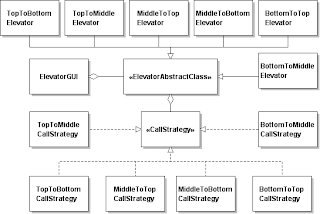
This UML class diagram does not show the classes involved in the GUI aspects of the application. This UML class diagram shows the classes involved in the behavior of the elevator - specifically how it handles a user "taking" the elevator to another floor and how a user "calls" the elevator from a floor different from the floor the elevator currently resides. The solution shown is available here.
Sunday, March 8, 2009
Challenge Four: Doktat's Elevator
Challenge Four involves an application that crudely simulates a three-floor elevator as shown in the schematic below. The code for the ElevatorGUIshell can be downloaded here. The challenge is to program this application without the use of any conditional logic.
 The application starts with the elevator at the first floor with 'GO' buttons enabled and 'CALL' buttons on floors two and three also enabled. At this point the elevator can go to the second or third floor in response to either the 'GO' buttons on the first floor or the 'CALL' buttons on either the second or third floors.
Assume the user has clicked on the 'GO TO 2nd FLOOR' button. The configuration of the elevator application should appear as shown in the figure below.
Having gone to the second floor, the 'GO' buttons on the second floor are now enabled and the 'CALL' button for the second floor disabled. The 'GO' buttons on the first floor are now disabled but the 'CALL' button for the first floor is now enabled. The configuration of the third floor remains unchanged. The textfield for the first floor indicates the door has now closed and the textfield for the second floor indicates the elevator has arrived, the door has opened and the user has exited.
Assume now that a user has clicked on the 'CALL' button on the third floor. The configuration of the elevator should appear as shown in the schematic below.
 Having arrived at the third floor the textfield indicates the elevator has arrived and the door has opened. Note that this message is different from the message shown when the elevator arrived at the second floor as the result of the user using the 'GO' button. Thus, the message shown is different in the textfield of the respective floor depending on whether the elevator was called to that floor or a user took the elevator to that floor. Again, the 'GO' buttons are now activated for the third floor but the 'CALL' button on the third floor is disabled. The textfield on the second floor indicates the door has closed and the 'CALL' buttons for both the second and first floors are enabled.
A solution employing no conditional logic will be available here.
 The application starts with the elevator at the first floor with 'GO' buttons enabled and 'CALL' buttons on floors two and three also enabled. At this point the elevator can go to the second or third floor in response to either the 'GO' buttons on the first floor or the 'CALL' buttons on either the second or third floors.
Assume the user has clicked on the 'GO TO 2nd FLOOR' button. The configuration of the elevator application should appear as shown in the figure below.

Having gone to the second floor, the 'GO' buttons on the second floor are now enabled and the 'CALL' button for the second floor disabled. The 'GO' buttons on the first floor are now disabled but the 'CALL' button for the first floor is now enabled. The configuration of the third floor remains unchanged. The textfield for the first floor indicates the door has now closed and the textfield for the second floor indicates the elevator has arrived, the door has opened and the user has exited.
Assume now that a user has clicked on the 'CALL' button on the third floor. The configuration of the elevator should appear as shown in the schematic below.
 Having arrived at the third floor the textfield indicates the elevator has arrived and the door has opened. Note that this message is different from the message shown when the elevator arrived at the second floor as the result of the user using the 'GO' button. Thus, the message shown is different in the textfield of the respective floor depending on whether the elevator was called to that floor or a user took the elevator to that floor. Again, the 'GO' buttons are now activated for the third floor but the 'CALL' button on the third floor is disabled. The textfield on the second floor indicates the door has closed and the 'CALL' buttons for both the second and first floors are enabled.
A solution employing no conditional logic will be available here.
Friday, March 6, 2009
Challenge Three: Depencency Inversion Principle and Retrofactoring
CHALLENGE THREE: DEPENDENCY INVERSION PRINCIPLE AND RETROFACTORING
CODE FOR THIS CHALLENGE (ZIP'D ECLIPSE PROJECT) AVAILABLE HERE.
The following are stated in Martin’s (2002, p. 127) discussion of the Dependency Inversion Principle (DIP).
a. "High-level modules should not depend on low-level modules. Both should depend on abstractions."
b. "Abstractions should not depend on details. Details should depend on abstractions."
The following schematics are recreations of figures from Martin (2002)
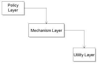 The problem with this configuration is that changing things in a lower layer, such as the Utility Layer can break things in the Mechanism Layer. Then Martin presents a preferred configuration.
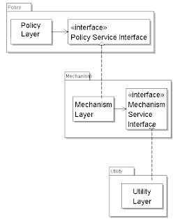 With the use of this configuration, Martin (2002, p. 129) states:
"Using this inversion of ownership, PolicyLayer is unaffected by any changes to MechanismLayer or UtilityLayer. Moreover, PolicyLayer can be reused in any context that defines lower-level modules that conform to the PolicyServiceInterface. Thus, by inverting the dependencies, we have created a structure, which is simultaneously more flexible, durable and mobile."
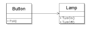
A more specific example is then presented when the discussion includes a switch controlling a lamp as shown in the shematic below.
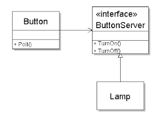
 Martin offers the following preferred configuration with inverted dependency.
 When preparing materials for my students, I often take refactored code and retrofactor it back to a point where they can then refactor it. In this challenge, I experienced an “ahah moment” when I was retrofactoring it and thought it might be useful to have the students try the same thing. The code I have provided has already been refactored to implement the dependency inversion principle (DIP). The schematic below shows the refactored configuration.
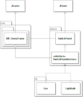
The student should remove the interface and configure the lamp (LightBulb or Fan) so that it is tightly coupled with the switch (SwitchPanel). To get the application to work, students should be aware of what must be done in terms of visibility/accessibility to establish the dependency?
CODE FOR THIS CHALLENGE (ZIP'D ECLIPSE PROJECT) AVAILABLE HERE.
The following are stated in Martin’s (2002, p. 127) discussion of the Dependency Inversion Principle (DIP).
a. "High-level modules should not depend on low-level modules. Both should depend on abstractions."
b. "Abstractions should not depend on details. Details should depend on abstractions."
The following schematics are recreations of figures from Martin (2002)
 The problem with this configuration is that changing things in a lower layer, such as the Utility Layer can break things in the Mechanism Layer. Then Martin presents a preferred configuration.
 With the use of this configuration, Martin (2002, p. 129) states:
"Using this inversion of ownership, PolicyLayer is unaffected by any changes to MechanismLayer or UtilityLayer. Moreover, PolicyLayer can be reused in any context that defines lower-level modules that conform to the PolicyServiceInterface. Thus, by inverting the dependencies, we have created a structure, which is simultaneously more flexible, durable and mobile."
A more specific example is then presented when the discussion includes a switch controlling a lamp as shown in the shematic below.
 Martin offers the following preferred configuration with inverted dependency.
 When preparing materials for my students, I often take refactored code and retrofactor it back to a point where they can then refactor it. In this challenge, I experienced an “ahah moment” when I was retrofactoring it and thought it might be useful to have the students try the same thing. The code I have provided has already been refactored to implement the dependency inversion principle (DIP). The schematic below shows the refactored configuration.
The student should remove the interface and configure the lamp (LightBulb or Fan) so that it is tightly coupled with the switch (SwitchPanel). To get the application to work, students should be aware of what must be done in terms of visibility/accessibility to establish the dependency?
Thursday, March 5, 2009
Challenge Two: Answer & Discussion
Many students quickly notice that the UML class diagram for the State Design Pattern is essentially the same as the Strategy Design Pattern. Both patterns use classes that provide concrete implementations of the desired behavior abstracted into an interface (or abstract class) . The primary difference between these two design patterns is the location of the responsibility for knowing what the next state should be when a certain action occurs. In a state diagram certain states can only transition to certain other states and when using the State Design Pattern , this knowledge is given to the concrete implementations of the classes representing these states.
Consider the following state diagram which displays the altered states incorporated into my refactored solution to the stopwatch challenge.
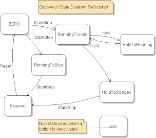
I have split the Running state into two states, RunningToHold and RunningToStop. Which state the running stopwatch is in depends on which button the user clicks to transition the stopwatch to its next state. If the user clicks on the ‘HOLD’ button, the stopwatch was in the RunningToHold state. If the user clicks on the ‘START/STOP’ button, the stopwatch was in the RunningToStop state. Likewise, for the same reason, the Hold state is partitioned into HoldToRunning and HoldToStopped states. These states have the responsibility for configuring what the current state is with respect to whatever button could be clicked in addition to controlling the clock. For example, consider the ZERO state.
The ZeroState class, which represents the state with name ZERO in the state diagram shown above, implements the execute method with the following code.
public void execute()
{
clock.start();
startStopButton.setCurrentState(runningToStoppedState);
startStopButton.setBackground(Color.green);
holdButton.setCurrentState(runningToHoldState);
holdButton.setBackground(Color.green);
// resetButton already set to nullState
}
After starting the clock, it prepares the Start/Stop button for what it should do next if the user were to click on Start/Stop. Likewise, it prepares the Hold Button. Since the Reset button will be unavailable and was already configured that way, no changes are made to the Reset button. For further discussion, assume the user will click on the Start/Stop button again after starting the watch. The RunningToStoppedState will be the state responsible for what is to happen next as shown in the following execute method.
public void execute()
{
clock.stop();
startStopButton.setCurrentState(nullState);
startStopButton.setBackground(Color.lightGray);
holdButton.setCurrentState(nullState);
holdButton.setBackground(Color.lightGray);
resetButton.setCurrentState(stoppedState);
resetButton.setBackground(Color.green);
}
After stopping the clock, the next state is the STOPPED state and the only button activated is the Reset button. Thus the Start/Stop and Hold Buttons are set to NullState and deactivated (colored gray) while the Reset Button is set to StoppedState and activated (colored green). Thus each transition to a new state in the stopwatch machine is accompanied by appropriate configuration of the buttons by activating/inactivating them and informing them what the next state of the machine is. There is no central control of the states of this machine via a monolithic conditional logic structure (the hallmark of procedural programming). If a new state was required, appropriate implementation of the execute method in the new state class plus adjustments in classes transitioning into the new class and out of the new class would be the only changes necessary.
In Challenge One, a Strategy Design Pattern was used to handle the two modes of the Bergin Swing Calculator. The refactored stopwatch also uses a Strategy Design Pattern to handle the two modes of the timer thread, suspended or running. This obviated the need for conditional logic to determine current state of the thread because with the use of the strategy, the thread already knew what state it was in and what to do.
The only conditional logic statements in the application are found in the Clock class where numbers are parsed and formatted. This is an example where conditional logic is not being used to determine the state of a class and hence control its behavior, and thus is out of the scope of the intent of the “Programming Without Ifs” exercises.
Subscribe to:
Posts (Atom)
